- English
- Español
- Português
- русский
- Français
- 日本語
- Deutsch
- tiếng Việt
- Italiano
- Nederlands
- ภาษาไทย
- Polski
- 한국어
- Svenska
- magyar
- Malay
- বাংলা ভাষার
- Dansk
- Suomi
- हिन्दी
- Pilipino
- Türkçe
- Gaeilge
- العربية
- Indonesia
- Norsk
- تمل
- český
- ελληνικά
- український
- Javanese
- فارسی
- தமிழ்
- తెలుగు
- नेपाली
- Burmese
- български
- ລາວ
- Latine
- Қазақша
- Euskal
- Azərbaycan
- Slovenský jazyk
- Македонски
- Lietuvos
- Eesti Keel
- Română
- Slovenski
- मराठी
- Srpski језик
Products


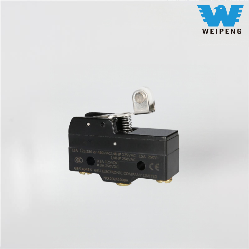
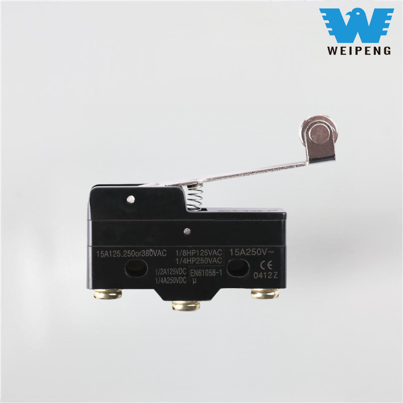
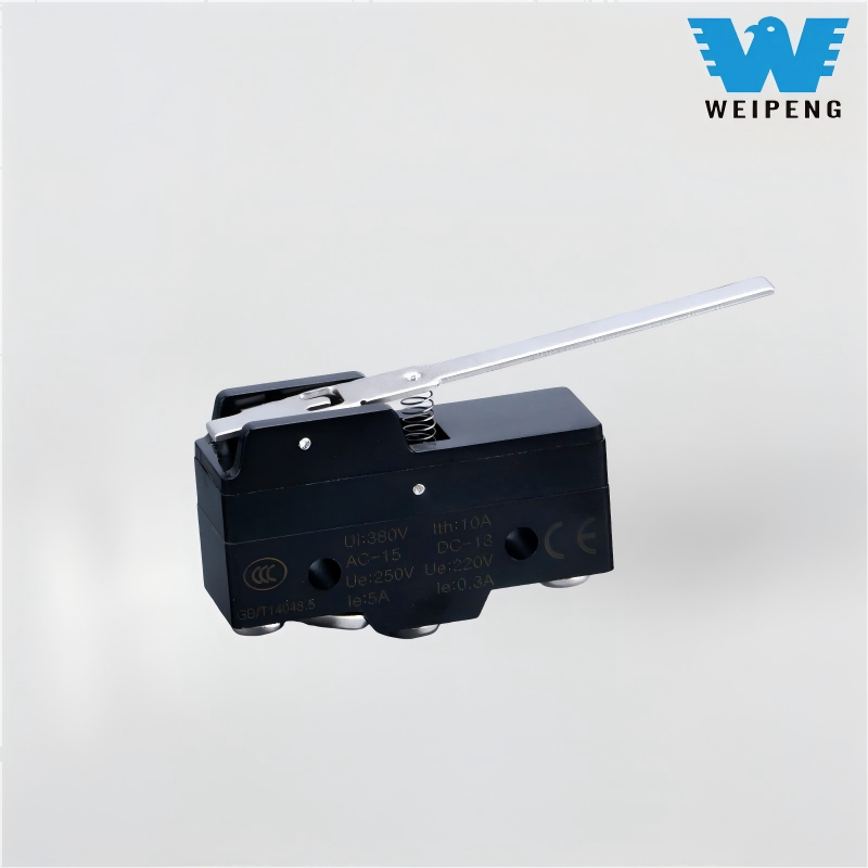
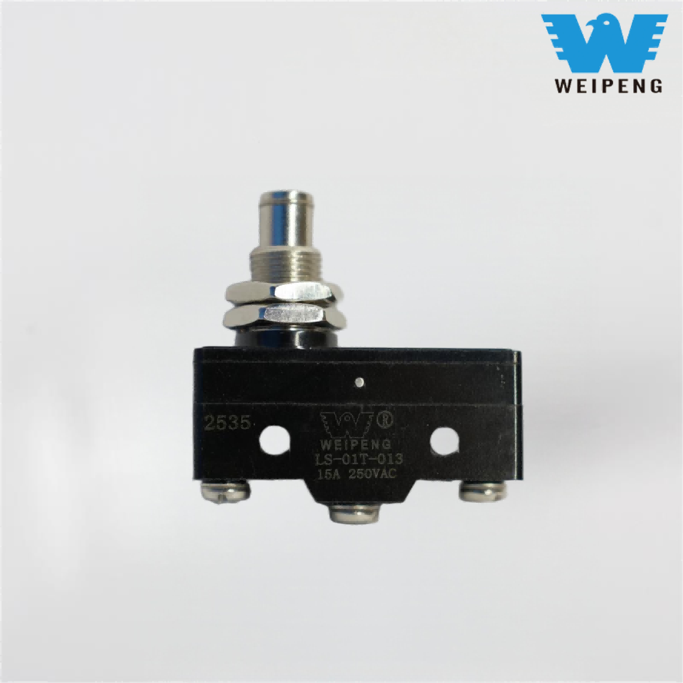
Silver Contact Stroke Limit Self-Resetting Switch
Silver Contact Stroke Limit Self-Resetting Switch typically comprises three parts: a triggering mechanism, a contact system, and a housing. The triggering mechanism makes direct contact with moving components, and when the component moves to a preset position, the triggering mechanism is activated by force to drive the internal mechanical structure, causing the contact system (normally open / normally closed contacts) to function, thereby disconnecting or connecting the control circuit. Some high-end models also incorporate waterproof sealing structures and corrosion-resistant housings, making them suitable for complex working environments.
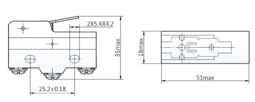
Model:LS-01-005
Send Inquiry
Product Description
WEIPENG® is a leading Silver Contact Stroke Limit Self-Resetting Switch manufacturers, suppliers and exporter.
Switch Introduction
A limit switch typically comprises three parts: a triggering mechanism, a contact system, and a housing. The triggering mechanism makes direct contact with moving components, and when the component moves to a preset position, the triggering mechanism is activated by force to drive the internal mechanical structure, causing the contact system (normally open / normally closed contacts) to function, thereby disconnecting or connecting the control circuit. Some high-end models also incorporate waterproof sealing structures and corrosion-resistant housings, making them suitable for complex working environments.
Switch Application
The top and bottom of the elevator shaft are both equipped with limit switches, known as travel switches, which serve as the "last line of safety" for the elevator. When the elevator malfunctions due to a control system failure, and the cabin approaches the top of the shaft (overhead) or the bottom (overload), the cabin triggers the travel switch, cutting off the main power supply of the elevator and activating the brake system to force the cabin to stop. Additionally, switches are also installed at both ends of the elevator door tracks to prevent the door from overshooting and getting stuck or crushing passengers.
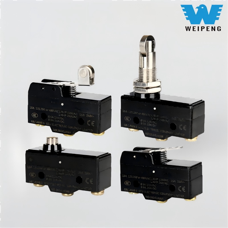
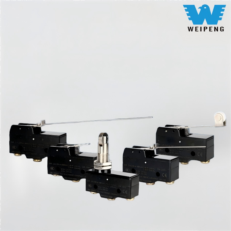
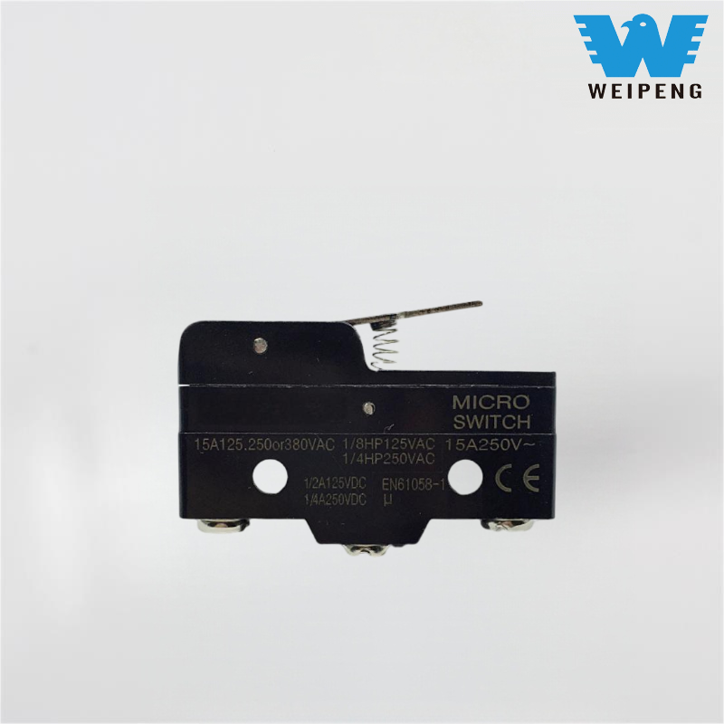
Switch Details
Hot Tags: Silver Contact Stroke Limit Self-Resetting Switch, China, Manufacturers, Suppliers, Wholesale, Factory, Price
Product Tag
Related Category
Micro Switch
Waterproof Micro Switch
Rocker Switch
Push Button Switch
Toggle Switch
Tactile Switch
Keyboard Switch
Reset Micro Switch
Piezo Switch
Limit Switch
Customized Switch
Send Inquiry
Please feel free to give your inquiry in the form below. We will reply you in 24 hours.