- English
- Español
- Português
- русский
- Français
- 日本語
- Deutsch
- tiếng Việt
- Italiano
- Nederlands
- ภาษาไทย
- Polski
- 한국어
- Svenska
- magyar
- Malay
- বাংলা ভাষার
- Dansk
- Suomi
- हिन्दी
- Pilipino
- Türkçe
- Gaeilge
- العربية
- Indonesia
- Norsk
- تمل
- český
- ελληνικά
- український
- Javanese
- فارسی
- தமிழ்
- తెలుగు
- नेपाली
- Burmese
- български
- ລາວ
- Latine
- Қазақша
- Euskal
- Azərbaycan
- Slovenský jazyk
- Македонски
- Lietuvos
- Eesti Keel
- Română
- Slovenski
- मराठी
- Srpski језик

Lighted Rocker Switch: Types, Wiring, and Buying Guide
An illuminated rocker switch serves as a kind of on/off switch that is incorporated with an LED or neon light, which indicates whether the switch is in the on/on position or not easily. Due to its indicator, the rocker switch is clearly visible even in the dark or cluttered control panels. The illuminated rocker switches have found their utility in many applications in cars, boats, RVs, bikes, household appliances, industrial machines, electrical control systems, etc.
It is possible to use illuminated rocker switches in both low voltage circuits and high voltage sectors. One may encounter 12V switches that are used in automotive applications as well as 120V AC switches for use in homes and industry. In choosing the appropriate type, the voltage of the system, current rating, type of load, terminal arrangement, size of the switch, and the area of installation need to be established.
What Is a Lighted Rocker Switch?
A rocker switch is made of a rocking mechanism which can activate an electrical circuit. The rocker switch is pushed to the on position, and the power supply connects to equipment being powered. Moreover, the switch has a built-in LED or neon to indicate power being switched on.
The switch can indicate whether it is receiving power, is turned on or if there is another circuit running, depending on the design and setup of the device. There are several different ways of connecting the switch, depending on the type. However, make sure to consult the wiring instructions and markers from the manufacturer before starting the installation.
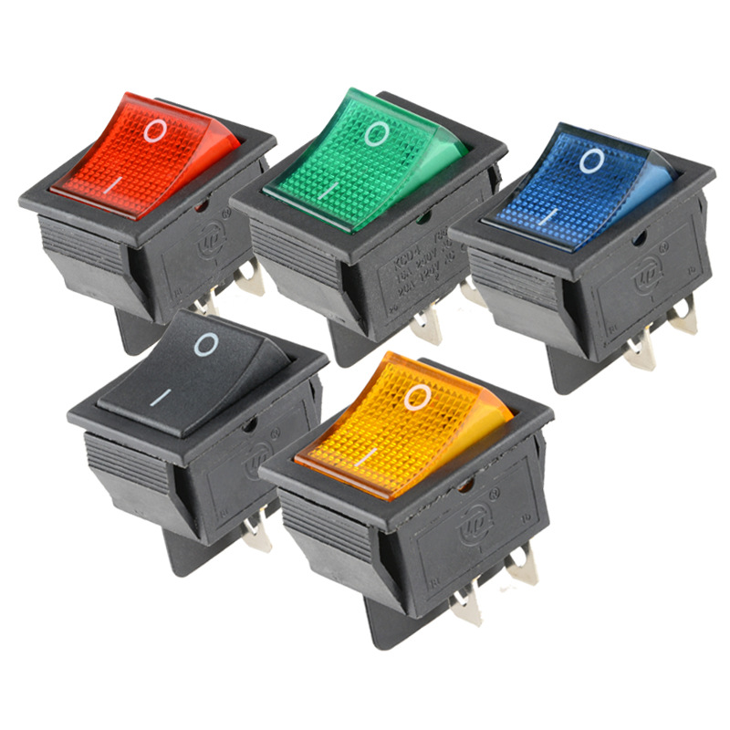
Common Types of Lighted Rocker Switches
Two-Terminal Rocker Switches
The two-terminal switch is designed to operate in the simple on and off mode. Generally speaking, this type of switching device connects with both the load and electric supply circuits and can light the LED when energized. Some LED types are influenced by polarity, so the connections must be done as described below.
Three-Terminal Rocker Switches
The three-terminal designs are characterized by provision for input of electrical energy, switchable signals, and connection for grounding. As a consequence of having a separate terminal for ground connection, the indicator under consideration can operate without problems. This type of design is frequently utilized in automobiles and boats.
Four- and Five-Terminal Rocker Switches
4 and 5 terminal switches can provide independent lighting, double-pole switching or multiple outputs. They are fit for more sophisticated control heads, although proper wiring depends upon the internal configuration of the circuit. Therefore, the diagram that is given should be followed instead of simplifying the wiring process through standard terminal places.
SPST, SPDT, and DPDT Configurations
The SPST switch has the capability of completing just one single circuit and switching it from on to off only. SPDT switches turn on one input and work on two outputs. DPDT switches operate on two circuits and are capable of selecting inputs or reversing polarity. The SPST switch is the most common form of switch used for typical applications, like switching on a lamp.
What Is a Lighted Rocker Switch 12V Used For?
A 12-volt rocker switch with illumination is designed for use in electrical circuits with a 12-volt direct-current (DC) supply. Typical applications include:
- Automotive and motorcycle lighting
- LED light bars and work lights
- Cooling fans and water pumps
- Boat and RV accessories
- Dashboard and control-panel equipment
- Battery-powered electrical systems
12V standard does not stipulate the upper current limit for the switch. It can be stated, for instance, that a switch can operate on 12V power at a current of 20A. However, during starting, certain machines such as motors and pumps might draw more current. For this purpose, proper relays must be used to control high currents or inductive loads.
How to Choose the Right Lighted Rocker Switch
Check the Voltage and Current Rating
Select a switch that will work properly with the voltage and current of the circuit. For example, a switch with a rating of 12V DC must not be used for a circuit with voltages of 120V or 230V AC. In addition to the normal operating current, one must also consider the starting or inrush current of the load.
Consider the Load Type
Electric motors, pumps, heating devices, light bulbs, and LED drivers impose different loads on switches. Ratings that consider only resistive loads may not apply to inductive loads such as electric motors. The selection of switches must be made according to the loads that they have to handle.
Confirm the Mounting Dimensions
Before ordering, ensure to check the measurement of the panel cutout as well as the thickness of the panel, position of the holding tab, and clearances from behind the panel. A switch may get into the cutout in front but may still collide with other parts and wiring.
Review the Indicator Specifications
The power consumption of LED indicators is very low, so they are usually used in 12V systems. Be sure that the LED contains an internal resistor and verify whether it has polarity. Using a switch with different voltage can cause the indicator to be oriented incorrectly.
Consider Environmental Protection
We should select switches that have an ability of resisting moisture and preventing rust in case they are going to be used outdoors, indoors, in a marine environment, or in environments with dust and vibration.
How Do You Wire a Lighted Rocker Switch?
Wiring a lighted rocker switch involves identifying the specifications of the particular switch, including its number of terminals and layout. Always cut off the power supply before beginning the work and identify each of the terminals accurately. The connection to the power mains should be performed by qualified technicians only.
Typical Three-Terminal 12V Wiring
Fused positive supply  ->  Power or input terminal
Switched output        ->  Positive terminal of the load
System negative        ->  Ground terminal and load negative
The electricity shall be available on the load as soon as the switch is turned on, indicating that the indicator has turned on. The fuselink must be mounted right next to the supply, i.e. the battery. The value of the fuse must also correspond to the type of wire and specification of the circuit.
Typical Two-Terminal Wiring
Positive supply   ->  Switch terminal 1
Switch terminal 2 ->  Load positive
Load negative     ->  System negative
When a switch includes a polarity-sensitive LED, it is important to connect the positive and negative leads correctly. In the event that the leads are reversed, the LED will not turn on, despite the fact that the switch will work correctly.
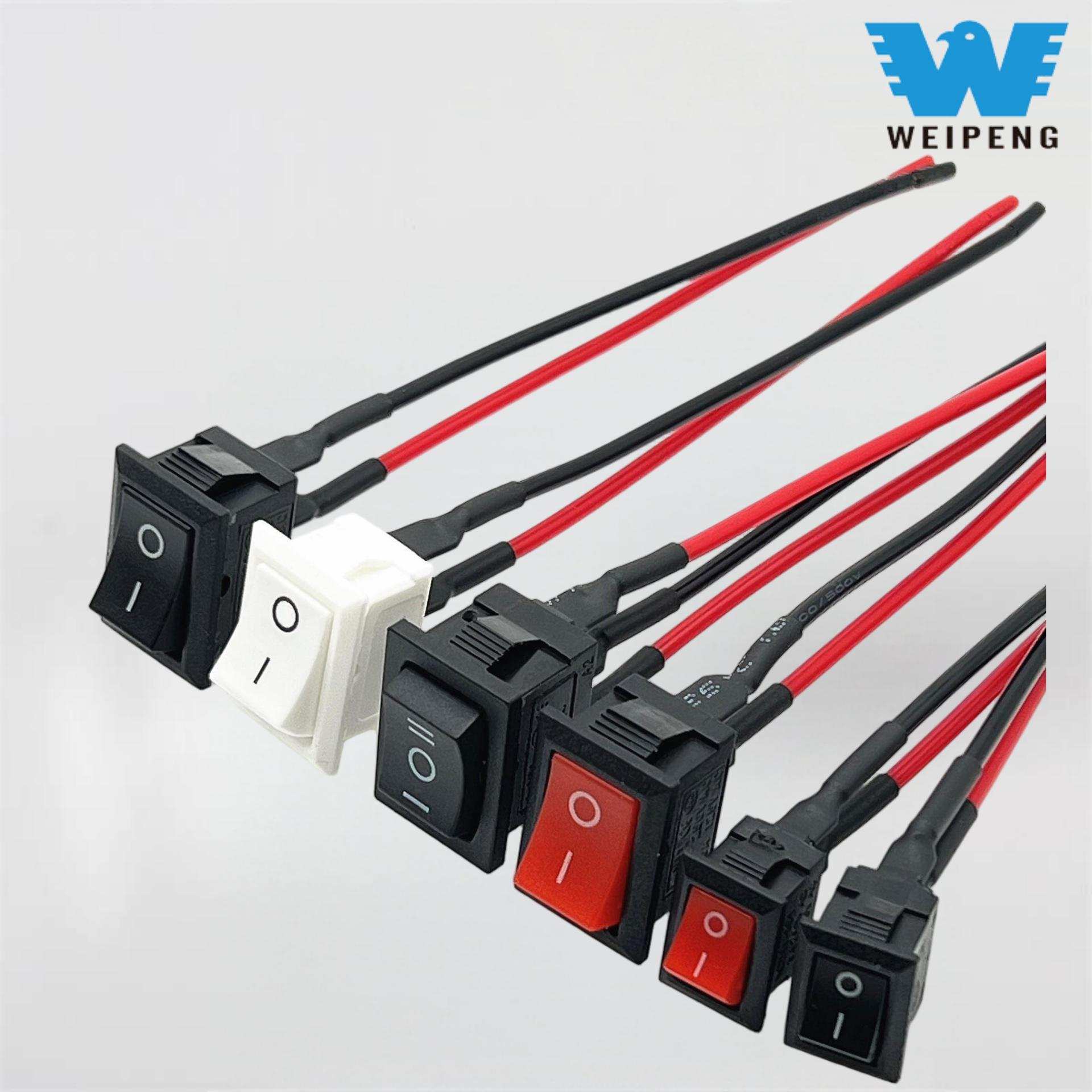
Wiring and Safety Considerations
Use a wire that comes with the proper current rating and make use of insulated terminals as well as heat shrink tubing to guarantee that all connections are safe. Don’t route wires close to sharp corners, high heat sources, or areas that may create movement. For vehicles, check that the wiring harness is not also exposed to vibrations and abrasions. For marine wiring, ensure that connectors as well as wires used are corrosion free.
A lighted switched rocker does not act as a replacement for a circuit breaker, the correct ground, or fuse. If the switch becomes too hot, melting, discoloring, sparking, or emitting the burnt smell, it should be turned off as it may be an indication of an electrical fault, such as excess current, loose connection, faulty contacts, or wires too thin to handle the load.
Common Lighted Rocker Switch Problems
The Indicator Does Not Illuminate
Some common reasons are reversal of polarity, missing a ground connection, error in identifying terminals, or using an indicator designed for a different voltage. Correctly compare the installation work with the manufacturer’s wiring diagram and verify that voltage is present on the right terminals.
The Load Works but the Indicator Does Not
Even if the switch contacts are well-conducted, it is equally important to check if the device has a separate ground or power supply. Also, check if the unit has a light source that functions separately from others.
The Indicator Remains On When the Switch Is Off
Some switch models operate in a way that they illuminate whenever power is present at their input. This behavior may be normal for that particular device. Before replacing the switch, make sure to check switch indicator circuit.
The Indicator Flickers or the Switch Becomes Hot
Issues such as loose connections, voltage drop, high current flow, or unsuitable loads could cause flickering and overheating. This should be investigated by disconnecting the circuit and examining the rating of the switch, the wire size, and how the device is connected and loaded. If needed, the use of a relay may be required for the motor, pumps, or other loads that draw high currents.
Frequently Asked Questions
Does a lighted rocker switch require a ground wire?
Not always is this the situation. With the case of two-terminal types of meters, they connect their indicator internally, which means that no separate grounding is necessary. Models having three terminals should always have their own ground point. Always verify the respective terminals and specifications of products.
Can a 12V lighted rocker switch control LED lights?
The assertion is valid since the switch has a rating that corresponds to the voltage of the system, rated operating current, and start-up current of the LED driver. A relay may be required when using bigger LED bars or several fixtures.
Can a 12V rocker switch be used with household power?
No, a rocker switch rated for 12V DC cannot be used with either 120V or 230V AC. An AC switch must be rated for AC voltage, current, types of loads, and applicable safety standards for household electricity.
Why does my LED rocker switch glow faintly when it is off?
A small leakage current from the gizmo or the load in the circuit produces dim light. At times instead of this arrangement one can resort to using a different switch or relay or device on the load’s side as well.
How can I test a rocker switch?
To test its continuity the switch must be removed from the power source and the multimeter set to continuity mode. The operation of the switch should be such that it has both open and closed responses during operation. Never conduct continuity testing on an energized circuit.
An adequately illuminated rocker switch has the specifications of voltage, current, type of load, terminals, size and function that fit its environment. To activate a small 12V accessory, an SPST switch is a suitable choice. If there are motors or heavy equipment involved, there will be a need for a relay, and there is also a need for fuses and appropriate wires in other electrical systems.