- English
- Español
- Português
- русский
- Français
- 日本語
- Deutsch
- tiếng Việt
- Italiano
- Nederlands
- ภาษาไทย
- Polski
- 한국어
- Svenska
- magyar
- Malay
- বাংলা ভাষার
- Dansk
- Suomi
- हिन्दी
- Pilipino
- Türkçe
- Gaeilge
- العربية
- Indonesia
- Norsk
- تمل
- český
- ελληνικά
- український
- Javanese
- فارسی
- தமிழ்
- తెలుగు
- नेपाली
- Burmese
- български
- ລາວ
- Latine
- Қазақша
- Euskal
- Azərbaycan
- Slovenský jazyk
- Македонски
- Lietuvos
- Eesti Keel
- Română
- Slovenski
- मराठी
- Srpski језик

Micro Switch 5a 125 250v
Micro Switch 5a 125 250v is a tiny snap action switch which is used for switching on and off electrical circuits upto the maximum of 5a at the specified operating limits with 125 v AC and 250 v AC. It is generally used in electronic appliances, control systems, vending machines, office equipment, doors and covers, appliances, etc.
Verify that besides the existing rating, the load type, actuator type, force, configuration of terminals, dimensions, and environmental conditions are suitable for the use you are planning for the components.
What Does 5A 125/250VAC Mean?
The designation “5A 125/250VAC” typically indicates that the switch can manage a maximum of 5 amps at a voltage of 125 volts AC or 250 volts AC if used with the appropriate load as recommended by the manufacturer.
This specification usually applies to resistive loads.
Devices such as motors, solenoids, compressors, lamps, transformers, and electronic power supply units may experience high inrush current or electrical arcing. In such cases it may be necessary to employ devices with a different load rating or application of an appropriate suppression device.
This represents an AC rating. However, this does not guarantee that the switch is approved for use at 125VDC or 250VDC. Always look for the distinct DC rating in the assigned datasheet before proceeding.
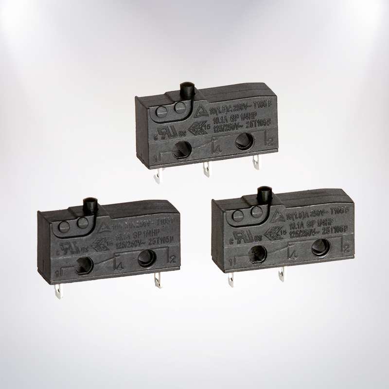
How Does a Micro Switch Work?
A micro switch employs a snap-action mechanism. The moment the actuator gets into the exact location, the inner spring changes contact state rapidly. Therefore, it allows excellent reliability of the switch despite its minimal motion and constant operating point.
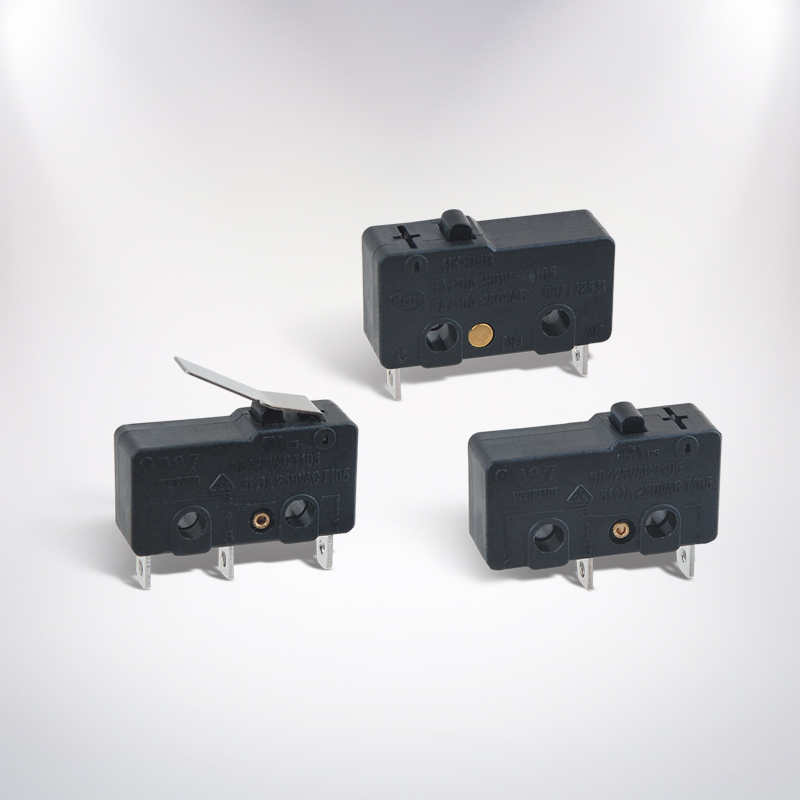
Among the typical types of actuators are the plunger, hinge lever, roller lever, and simulated roller. The appropriate type of actuator is selected based on the available space, direction of movement, and force and distance needed for the process.
SPDT Terminal Configuration
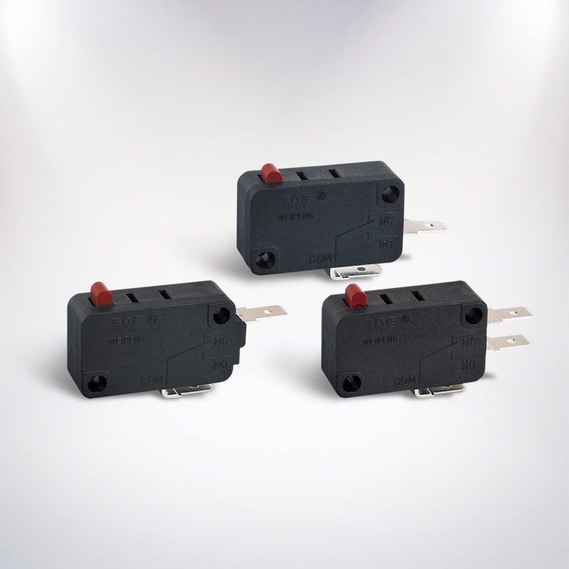
Several 5A models operate in SPDT mode (Single Pole Double Throw). The common terminals in SPDT are COM, NC, and NO.
| Terminal | Function |
|---|---|
| COM | Common connection |
| NO | Normally open; connects to COM when pressed |
| NC | Normally closed; disconnects from COM when pressed |
When the circuit is activated with the pressing of the actuator, employ COM in conjunction with NO. On the other hand, utilize COM in combination with NC when the circuit should remain closed in a standby state, and becomes open when the actuator is engaged. Be sure to verify the labelling on the actual switch before the wiring process.
What Is a Sensitive Micro Switch?
A micro switch that is sensitive operates with quite low force. It is useful whenever the switch is actuated with the help of a light door, plastic tab, small mechanism, or limited movement.
Sensitivity is determined by more than the current rating. Check the following specifications:
- Operating force and release force
- Pretravel and overtravel
- Operating position
- Actuator type and length
- Mechanical and electrical life
The use of a roller lever can minimize the effort needed from the external system. However, improper alignment can lead to lateral stress and early failure. It should work properly, operating without exceeding its overtravel specification.
5A, 10A, 16A, and 21A Micro Switches
Micro switches are manufactured in different versions of current ratings, namely 5A, 10A, 16A, and 21A. Higher current rating is not necessarily the right choice; it is paramount that the switch must keep in line with application voltage, load type, measurements, type of terminal and standards.
| Rating | Typical use | What to check |
|---|---|---|
| 5A | Signal circuits and smaller resistive loads | Voltage, load type, and switching frequency |
| 10A | Higher-load control and appliance applications | Inrush current and electrical life |
| 16A | Applications requiring greater contact capacity | Temperature rise, wiring, and certification |
| 21A | Specialized higher-current applications | Exact tested load and installation conditions |
When you are looking at a Micro Switch rated at 5A at both 125V and 250V with other models rated at 10A, 16A, and 21A you should compare all the specifications rather than only looking at the rating. The higher rated switch may differ from the lower rated models in design features such as mounting holes, actuator travel, terminal position and contact dimensions.
Load and Safety Considerations
Before connecting the load, it is necessary to identify not only the normal current but also the inrush or startup current. Resistive loads are normally much easier to deal with than inductive or capacitive loads. Motors and solenoids may generate sparks that could harm the contacts even though the normal current is below 5 A.
In main applications, appropriate insulation, overload protection, mechanical protection and enclosure should be used. Proper installation of the switch should normally be done so that it breaks the conducting wire as specified by the equipment design and local electrical regulations.
Before the installation or testing work in this regard, disconnect the mains supply. The wiring of mains voltage should either be completed or inspected by a qualified professional.
Mounting and Installation Tips
Always check the body dimensions, mounting-hole spacing, actuator height, terminal type, and operating position prior to ordering. Switches that look similar are not necessarily interchangeable.
The actuator has to be pressed in the correct direction and it must not be used as a hard mechanical stop unless indicated otherwise by the manufacturer. Excessive impact, side pressure, humidity, moisture, and vibrations must be avoided.
There are different kinds of commonly used terminals; they include solder terminals, quick connect tabs, PCB pins and wire terminals. The style can be chosen based on the assembly technique used and the availability of space.
How to Choose the Right Model
Use this checklist before purchase:
- Confirm the AC or DC voltage and actual load current.
- Identify whether the load is resistive, inductive, capacitive, motor, or lamp.
- Select SPDT, SPST-NO, or SPST-NC according to the circuit.
- Choose the required operating force and actuator style.
- Compare mounting dimensions and terminal positions.
- Check operating temperature, sealing, electrical life, and approvals.
- Request the official datasheet for the exact part number.
FAQ: Sensitive Micro Switch SPDT 5A 125/250VAC
What is a sensitive micro switch SPDT 5A 125/250VAC?
The switch is a low-force and snap-action device with a common terminal and dual outputs. Its maximum current rating is 5A when operated under controlled conditions.
Can I use it for 250VDC?
No, while the marking of 125/250 VAC does represent an AC rating, it does not give a rating for DC voltage. Always look for a switch with a DC voltage and current rating mentioned.
What is the difference between NO and NC?
The normally open switch allows electricity to flow when nothing is pressed on the switch, while the normally closed switch allows electricity to flow when the actuator is pressed.
Can a 5A micro switch control a motor?
Although the current of the motor is under 5A, the switch may not work correctly. Identify the starting current and inductive arcing which may exceed the capacity of the switch. Value the load capacity of the motor or use a relay or a contactor.
Can I replace a 5A switch with a 16A or 21A model?
It is only if the replacement has the same size in terms of dimensions, actuator movement, terminal arrangement, contact arrangement, voltage rating, and certification. A greater power rating in itself is not enough.
How long does a micro switch last?
The life of a product is determined by load, frequency of message, alignment, environment and quality of installation. Mechanical and electrical life are distinct terms; therefore the electrical life specifications should be followed accordingly with respect to the actual load.
To conclude, the Micro Switch 5a 125 250v is a viable option for small-sized AC control and position-sensing systems if the load and mechanical parameters are appropriate. Verify the specifications, choose the right terminals and actuator for SPDT, and resort to using a relay or a heavy-duty solution for devices with significant inrush current or for demanding electromechanical applications.